MR-02 PCB help needed
- SuperFly
- bitPimp
- Posts: 2760
- Joined: Mon May 05, 2003 6:37 pm
- Location: nationwide
MR-02 PCB help needed
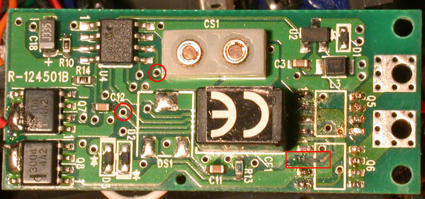
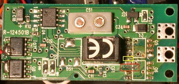
My MR-02 PCB is fucked, but I think salvagable. As you can see in the red rectangle, my pad is destroyed/gone as well as a little of the trace coming away from it.
I have a whoa nelly waiting to install, or I could put some new fets back in. Is there a place in the C12 area I could tap into instead of that pad? Any advice welcome.

I have a whoa nelly waiting to install, or I could put some new fets back in. Is there a place in the C12 area I could tap into instead of that pad? Any advice welcome.

- Zenith
- bitGangsta'
- Posts: 455
- Joined: Sun Jun 19, 2005 10:15 pm
- Contact:
- SuperFly
- bitPimp
- Posts: 2760
- Joined: Mon May 05, 2003 6:37 pm
- Location: nationwide
hehe, that's just some solder sloppiness. The trace keeps on running under the black box and out the other side, but I'm not sure which of the traces coming out from under the black box on the left side it is.
My thought is that I could solder on to where it goes through the PCB (those little circles) to the other side of the board.
My thought is that I could solder on to where it goes through the PCB (those little circles) to the other side of the board.
- Zenith
- bitGangsta'
- Posts: 455
- Joined: Sun Jun 19, 2005 10:15 pm
- Contact:
-
sg219
- bitPimp
- Posts: 4245
- Joined: Thu Jan 22, 2004 1:00 pm
- Location: Kennywood, PA
- Contact:
- SuperFly
- bitPimp
- Posts: 2760
- Joined: Mon May 05, 2003 6:37 pm
- Location: nationwide
I agree about soldering to the other side. There just has to be a spot that's nice and sturdy somewhere else on that PCB. I've seen people fix MR-01 boards that way, by going over near the C12 area, but the MR-02 board is different enough that I need someone smarter than me to tell me where that is.sg219 wrote:Not much of a geek, but I think soldering to the other side might be your best bet.
Don't they sell something at RS that makes or replaces the tracing?
Yeah, they do make a pen that will draw conductive ink, so to speak. The problem is that whatever route I go, I need to be able to solder to it. That would work if I just had a break in the trace, but I need to stick either a fet or a Nelly wire to it.
-
richh
- bitGangsta'
- Posts: 279
- Joined: Fri Aug 27, 2004 9:31 am
it looks like some of the solder mask is already gone to the right of where the pad used to be. i would just solder some fine gauge hook up wire there, running the other end of the wire to the left. then solder fet back down (7 of the 8 legs that is), and then bend the wire back over and solder it to the last leg. then add a little hot melt or epoxy on the wire and it should hold.
depending on the wire you end up using, you might have to bend the legs down a little to clear the wire.
depending on the wire you end up using, you might have to bend the legs down a little to clear the wire.
- LBRC
- bitGangsta'
- Posts: 361
- Joined: Sun May 02, 2004 1:25 am
- Location: North West
- Contact:
Option one, use a multimeter to find the correct “via” that’s the hole where it runs though to the other side of the circuit board and connect the jumper there. Better than trying to run a jumper under the FET or even off a run.
Option two, good time for a Whoa Nelly, then you could solder the hookup wire directly to the run, securing it with non corrosive RTV, or from the via.
Option two, good time for a Whoa Nelly, then you could solder the hookup wire directly to the run, securing it with non corrosive RTV, or from the via.
- SuperFly
- bitPimp
- Posts: 2760
- Joined: Mon May 05, 2003 6:37 pm
- Location: nationwide
That's what I'm going to do. I multimeter tested the vias, and these two beeped. I just need to run a little jumper from one of the circled vias (it goes to the other side out the lower one and back in through the upper one). What is RTV? It sounds really useful.LBRC wrote:Option one, use a multimeter to find the correct “via” that’s the hole where it runs though to the other side of the circuit board and connect the jumper there. Better than trying to run a jumper under the FET or even off a run.
Option two, good time for a Whoa Nelly, then you could solder the hookup wire directly to the run, securing it with non corrosive RTV, or from the via.

- Zenith
- bitGangsta'
- Posts: 455
- Joined: Sun Jun 19, 2005 10:15 pm
- Contact:
- LBRC
- bitGangsta'
- Posts: 361
- Joined: Sun May 02, 2004 1:25 am
- Location: North West
- Contact:
- sat4life27
- bitPimp
- Posts: 404
- Joined: Wed Apr 27, 2005 10:48 am
- Location: Warner Vegas, GA
I had the same thing happen in the same spot with a mr01 board. I just used a small piece of wire and scratched off a little piece of the coating on the board right next to where it broke. Soldered it to it and then soldered the fet to the small piece of wire. After that I used a little bit of hot glue to cover it and protect the wire. I did that to the pcb I am using in the Import racer.
- SuperFly
- bitPimp
- Posts: 2760
- Joined: Mon May 05, 2003 6:37 pm
- Location: nationwide
After the "eureka" moment of realizing all those little holes (vias) are just like sockets to poke jumper wires into, I had my pcb back up and running in no time. As long as you have some shred of original trace to touch a multi-meter with a circuit-checker to, you can just test all those vias till you find the right one. After I got back into mine, I realized I actually had 2 destroyed pads, not just the one. 2 jumpers later and I have a nellified MR02 pcb.


