The DIP Switch Mod
by ph2t
For ages I’ve been looking for a switch that is small enough to be able to put on my little beasts to be able to turn them ON and OFF.
I know that the car doesn’t really NEED a switch, but hey! that’s never stopped me before. ;)
Basically the goal is to be able to take the battery out of circuit and charge it without any excess current drain from the PCB/lights.
Theoretically you should get a slightly increased runtime from the extra charge the battery would get but I believe this difference would only be small.
Another advantage is to be able to turn the car off and pick up later with no issues of battery loss.
So here it is, my DIP Switch mod.
Find the right switch
Here’s a DIP switch, not much to look at hey.
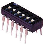
This is obviously too big, but you can saw off a single switch! I used a metal saw to do this since the cutting blade is finer and causes less damage to the surrounding area. If everything works you should have some pieces like this.

The flywheel helps give you an idea of the switch’s size.
Where do I mount the bloody thing?
The best place I found was underneath the engine well. This means the switch is out of sight, out of mind. I’ve drilled two holes in the vertical part of the chassis adjacent to the engine well. This is where I’ll feed to wires back to the battery.
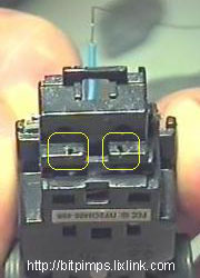
Here’s a side view to help give you an idea of how the switch is mounted. You can see from this side profile that the clearance to the ground is juuuuuuuust fine, yeah!

The little metal ends of the switch were cut back till only 2mm long. I then soldered some enamelled wire to the ends. I use this wire ’cause it’s flexible and small.
If you want to use normal insulated wire that’s fine but find some that is thin enough ’cause the wires could rub against the rear axle causing all sorts of problems.
Here’s two pictures showing the bugger all clearance between the wire and rear axle.
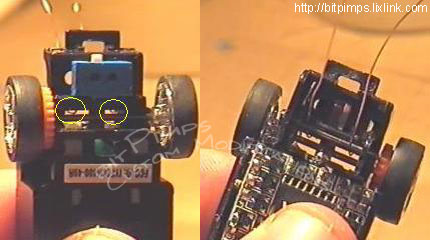
Now feed the wires up and over one of the notches in the chassis as shown below. These notches are on all classes of legit bits.
Solder time!
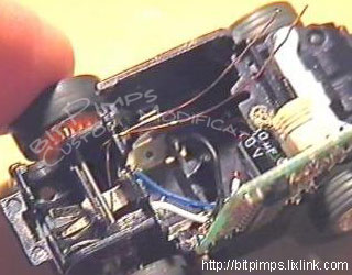
Ok, first thing to do now is to remove the -VE/GND/NEGATIVE power wire from the PCB and battery terminal.
Now solder one of the wires from the switch (doesn’t matter which one) to the battery terminal and the other wire to the -VE terminal on the PCB.
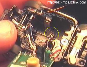
To the right, you can see (barely!) where I soldered the wire from the DIP switch.
Once that is done put the car back together and all should be cool.
Q.E.D