
Off-Road Bits – Part 3: Rear Shock
by betty.k
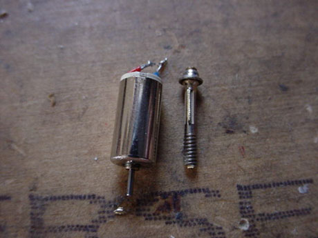
You’ll need a screw first, roughly this size. This screw is from a bike valve, but the important thing is that the thread covers the bottom half of the shaft and that the top has a head.

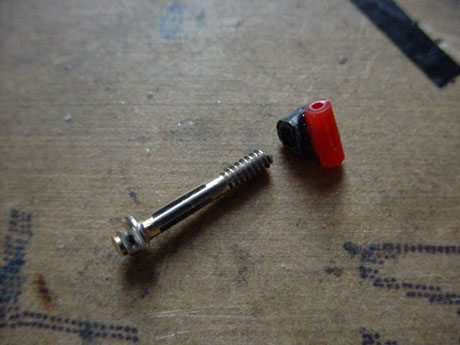
Find some scrap plastic. If it has a hole in it that the screw can screw into, that would be easier but it’s not necessary.

That’s all you need. Just a small block of plastic that screws onto the tip of the screw.

Cut a short section of tubing from a wd40 can, and find some strong wire such as a paperclip. The paperclip should move freely inside the tubing, but with minimal play.

Using a file, concrete, sand paper, whatever, shape the plastic block with a rounded end on one side and a bit of a groove cut at a 90 degree angle to the screw on the other. The groove is for the tubing to rest in.

Using blu tack as a jig, place the tubing horizontally, then the screw/plastic assembly on top vertically, with the groove in the plastic resting on the tubing. Make sure the screw and tubing are at right angles with each other, leaving the paperclip shaft in makes this easier. Apply good quality superglue to the plastic/tubing join and allow to dry. Don’t let ANY glue go into the tubing.
When dry, remove from the blu tack and apply more glue to the join and all the way around the tubing, being careful to avoid getting any glue inside the tubing.

See? Lots’a glue outside the tubing, none inside.

I’ve prepared this chassis for a dual cell. Find 2 short flat strips of plastic, and make sure the pivot rail (paperclip) is a little wider than the chassis, say 1.5 – 2mm.

Shape the plastic strips like this. A wide end and a narrow end. Make a hole in the narrow end that the pivot rail can fit snugly in.

Glue a plastic strip onto the chassis by the wide end so the hole sits back about 1.5mm from the end of the chassis and up about .5mm.

Slide the pivot rail into the plastic strips through the holes and use the rail as a reference so the second plastic strip is glued straight. The rail must be straight.

Slide the shock onto the pivot rail, insert the rail into the holes and glue the rail in place at each end. Make sure the shock shaft (screw) is on top.

Install the rear end with the heat sink in and line up the shock to see roughly where the screw head lines up on the heat sink.

Find a strip of metal and bend it like this. You need to make 1 hole big enough for the shock shaft to fit through but not the screw head. The other hole is for a screw.
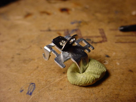
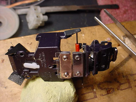
Attach the metal bit on the heat sink, making sure the shock mount sticks up where the screw head lined up. This heat sink is aluminum, so I can’t get solder to stick to it. So I?ve screwed the shock mount on. But with a steel heat sink, I?d solder it in place.

More plastic. This is going to be the adjustment dial.

Nearly there! Install the heat sink, and poke the screw through the shock mount from the rear.
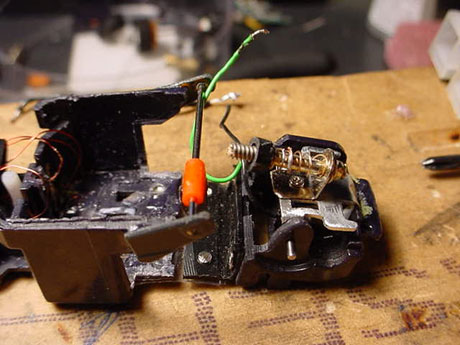
Slide your spring over the screw, then screw on the adjustment dial.

Screw the assembled shock into the pivot, and bang! You’re done!

The assembled rear end, uncompressed.

….and compressed. Preload is adjustable via the plastic dial.

Top, rear view.
Bottom left side. Now jam some FETS, a couple’a batteries, and some knobbies onto this sucker and hit tha’ dirt!
