
Add two more TX/RX Channels to your LXX Bit
-
jevries
- Posts: 5
- Joined: Tue Mar 23, 2004 6:40 am
-
ph2t
- bitPimp
- Posts: 1979
- Joined: Tue Mar 25, 2003 6:33 am
- Location: taco city
sorry dude, late reply.
you don't need any extra items at all. You just solder a wire to the output pins for the extra two channels and take it from there. If were going to drive a motor or any other high current sinking device (not LEDS!) then you should use a transistor/mosfet first to turn on and then use that to turn on the motor/dvice in question.
To drive LED's you don't need to do anything. The RX6C chip can handle the current LED's need to light up.
ph2t.
-
Maxximum Attack
- bitDisciple
- Posts: 1798
- Joined: Thu Jul 31, 2003 7:15 pm
- Location: Barbados
Sorry dude I recently asked him and he said he didn't have them. I'll post some pics that betty.k gave me and hope that helps. I was thinking of doing this mod too.
I'll edit this post with the pics once they're uploaded
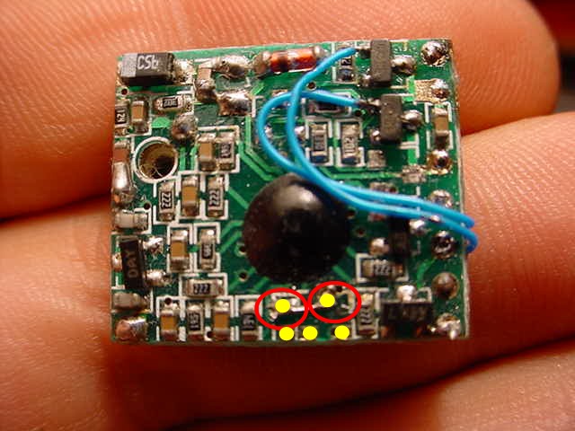
this first pic shows you how to wire up f1 on a tomy booster/ microsizer pro pcb. the yellow dots mark unused solder tabs on the pcb. you need to solder a wire between the 2 pads circled in red.
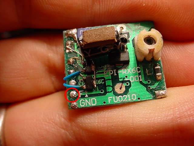
in this pic the f1 tab is circled in red. if you want an led on the extra channel you would solder the v+ leg to the f1 tab and the v- to the GND tab.
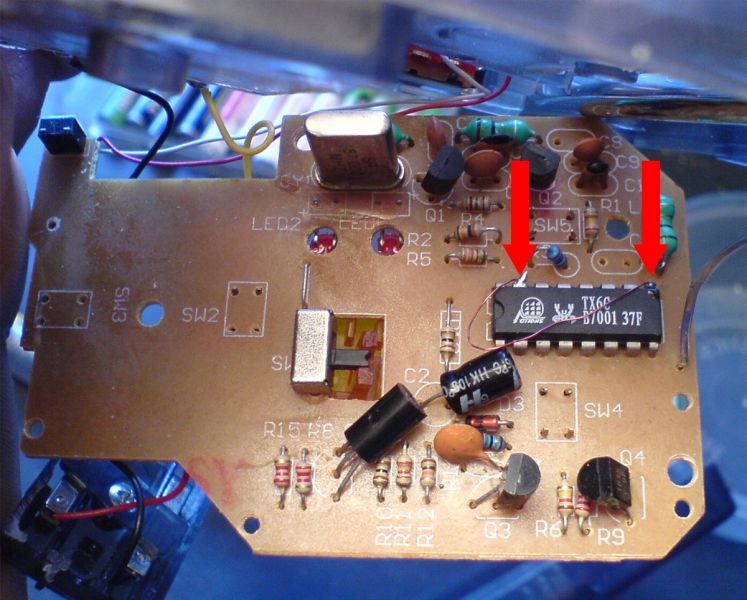
here we have the insides of an lxx tx with the tx6c chip. the red arrows point to (from l-r) pins 15 and 9. these are the pins that you wire to a switch then to v- on the pcb in order to activate the extra channels. (ignore the wiring in this pic)
f1 is pin 15, f2 is pin 9.
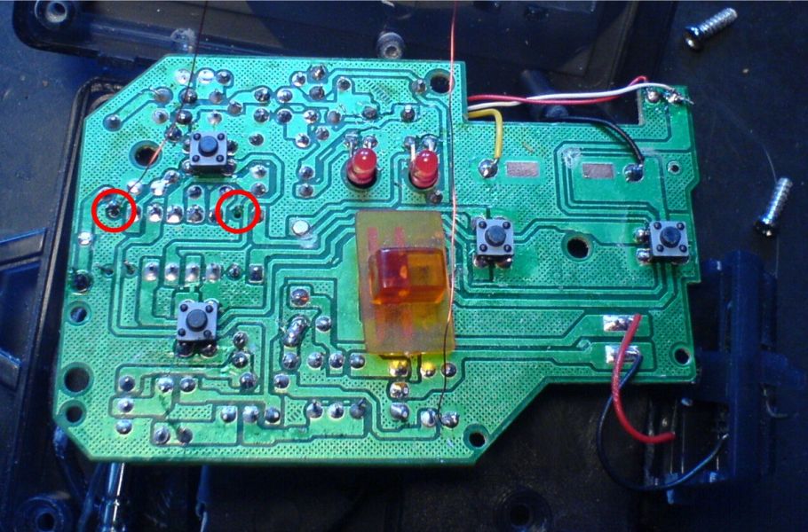
this is the other side of the tx pcb showing the pins (from l-r, circled in red) 9 and 15.
continued in my post below - betty.k
Welcome
Maxx
I'll edit this post with the pics once they're uploaded
this first pic shows you how to wire up f1 on a tomy booster/ microsizer pro pcb. the yellow dots mark unused solder tabs on the pcb. you need to solder a wire between the 2 pads circled in red.
in this pic the f1 tab is circled in red. if you want an led on the extra channel you would solder the v+ leg to the f1 tab and the v- to the GND tab.
here we have the insides of an lxx tx with the tx6c chip. the red arrows point to (from l-r) pins 15 and 9. these are the pins that you wire to a switch then to v- on the pcb in order to activate the extra channels. (ignore the wiring in this pic)
f1 is pin 15, f2 is pin 9.
this is the other side of the tx pcb showing the pins (from l-r, circled in red) 9 and 15.
continued in my post below - betty.k
Welcome
Maxx

-
Henal
- Posts: 7
- Joined: Sun Dec 17, 2006 7:15 am
thanks m8 i havent got that board but will try to do some thing with it
here is how mine is
http://img177.imageshack.us/img177/1168 ... onedt9.jpg
here is how mine is
http://img177.imageshack.us/img177/1168 ... onedt9.jpg
-
betty.k

- bitPimp
- Posts: 4090
- Joined: Fri Dec 26, 2003 4:52 pm
- Location: la la land
- Contact:
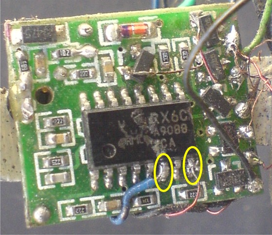
here is the fabled lxx 2 speed pcb with the rx6c chipset.
circled in yellow (from l-r) are pins 6 and 8.
pin 6 is f1, pin 8 is f2.
so in the case of the pictured pcb i have f1 wired to 2 rear mounted red led's and f2 wired to 2 forward facing white led's.
and on the tx i have a switch wired between pin 9 and v-, pin 15 and v-.
this gives me seperate radio controlled front and rear lights.
i used to be cool
