
A MAXXA Designs WIP
-
honda_s2000
- bitNinja
- Posts: 883
- Joined: Sat Oct 30, 2004 5:42 pm
- Location: New Zealand
-
Maxximum Attack
- bitDisciple
- Posts: 1798
- Joined: Thu Jul 31, 2003 7:15 pm
- Location: Barbados
*poof* This board needs a kick in the nuts....
Major update:
Well, it's been a while since I've updated with pics. Wait no longer
I've gotten the body itself to an acceptable state so I've decided to move onto the chassis in the meanwhile.
So it's time to gut it, cuz it's going under the knife

Buzzzzzzzzzzzzzz, buzzzzzzzzzzzzzzzzzz, buzzzzzzzzz

Here's what I'm going for. I've run into a little snag but I know how to over come that. I'll explain the snag in a bit...

Well, the first snag is that I can't keep the PCB flat and still have the rear wheels attached. Because that corner of the PCB is where the ground wire is attached, I can't even trim it so that the gear would be free to move. So I have to slant it like so...

Problem with the slant is that the PCB still 'rests' on the gear which stops it from turning. So I'll have to shim it slightly. I may not have to tho, because when I run the wires under the PCB it may provide the spacer effect I need.
Oh, by the way, to get the PCB tucked in so neatly you have to cut a notch at the bottom of the column that holds the screw for the steering cover, and also remove the walls from the slanted part of the chassis that is behind the front wheels.
Here is a mock-up of what the finished assembly should look like. Is it just me or does this scream 'lipo-mod' to you too?

Here is a side-by-side with a stock bit. This was just to give a height comparison. Notice anything funny about the cell?

Primer anyone?

I think I'll keep the rest of the cards to myself for now. This was by no means a full expose'
Time for me to disappear from the boards again and get to some school work
Comments always welcome.
Maxx
hope everyone misses me *poof*
Major update:
Well, it's been a while since I've updated with pics. Wait no longer
I've gotten the body itself to an acceptable state so I've decided to move onto the chassis in the meanwhile.
So it's time to gut it, cuz it's going under the knife
Buzzzzzzzzzzzzzz, buzzzzzzzzzzzzzzzzzz, buzzzzzzzzz
Here's what I'm going for. I've run into a little snag but I know how to over come that. I'll explain the snag in a bit...
Well, the first snag is that I can't keep the PCB flat and still have the rear wheels attached. Because that corner of the PCB is where the ground wire is attached, I can't even trim it so that the gear would be free to move. So I have to slant it like so...
Problem with the slant is that the PCB still 'rests' on the gear which stops it from turning. So I'll have to shim it slightly. I may not have to tho, because when I run the wires under the PCB it may provide the spacer effect I need.
Oh, by the way, to get the PCB tucked in so neatly you have to cut a notch at the bottom of the column that holds the screw for the steering cover, and also remove the walls from the slanted part of the chassis that is behind the front wheels.
Here is a mock-up of what the finished assembly should look like. Is it just me or does this scream 'lipo-mod' to you too?
Here is a side-by-side with a stock bit. This was just to give a height comparison. Notice anything funny about the cell?
Primer anyone?
I think I'll keep the rest of the cards to myself for now. This was by no means a full expose'
Time for me to disappear from the boards again and get to some school work
Comments always welcome.
Maxx
hope everyone misses me

-
SHAUN
- bitDisciple
- Posts: 1462
- Joined: Wed Oct 05, 2005 10:35 am
- Location: On the trail
- Contact:
-
honda_s2000
- bitNinja
- Posts: 883
- Joined: Sat Oct 30, 2004 5:42 pm
- Location: New Zealand
-
Bird

- bitPimp
- Posts: 1303
- Joined: Sat Jan 17, 2004 2:22 am
- Location: waste mifflin, pa
Nuh uhh... that's an SE cell...ibjamn wrote:Yeah, you're gonna have short run timesMaxximum Attack wrote: Notice anything funny about the cell?
@the idler clearance issue... got any KIT Racer gears?
The wbk EVO is already stunning in primer... can't wait to see some of that beautiful maxxa designs paintwork on it.
*poof*
-
ibjamn

- bitDisciple
- Posts: 1057
- Joined: Thu Mar 30, 2006 9:09 pm
- Location: right here, waiting
ummm.....what's with the genie in a bottle stuff?Bird wrote:Nuh uhh... that's an SE cell...ibjamn wrote:Yeah, you're gonna have short run timesMaxximum Attack wrote: Notice anything funny about the cell?
*poof*
but you're right, it's an SE cell, 2.4v 70mah.
which will be shorter runs than a 1.2v 100mah,..........at least I thought
-
Bird
- bitPimp
- Posts: 1303
- Joined: Sat Jan 17, 2004 2:22 am
- Location: waste mifflin, pa
Well, yeah, but the increase in performance outweighs the loss of runtime IMHO...ibjamn wrote:ummm.....what's with the genie in a bottle stuff?Bird wrote:Nuh uhh... that's an SE cell...ibjamn wrote:Yeah, you're gonna have short run timesMaxximum Attack wrote: Notice anything funny about the cell?
*poof*
but you're right, it's an SE cell, 2.4v 70mah.
which will be shorter runs than a 1.2v 100mah,..........at least I thought
-
ibjamn
- bitDisciple
- Posts: 1057
- Joined: Thu Mar 30, 2006 9:09 pm
- Location: right here, waiting
Agreed, so stuff a ZZMT battery pack in there, MAXX!
wait a min. if you do that, you might still fit the pcb on top of the MT pack stuffed in the middle. And that would take care of the gear clearance issue. But add a whole lotta weight.
nevermind, you know what you're doin,
I'll just shut-up and watch.............

wait a min.
nevermind, you know what you're doin,
I'll just shut-up and watch.............
-
PUBE JOOLZ

- bitGangsta'
- Posts: 200
- Joined: Thu Jul 27, 2006 12:27 am
- Location: Pasig, Philippines
- Contact:
-
Maxximum Attack
- bitDisciple
- Posts: 1798
- Joined: Thu Jul 31, 2003 7:15 pm
- Location: Barbados
-
honda_s2000
- bitNinja
- Posts: 883
- Joined: Sat Oct 30, 2004 5:42 pm
- Location: New Zealand
-
Maxximum Attack
- bitDisciple
- Posts: 1798
- Joined: Thu Jul 31, 2003 7:15 pm
- Location: Barbados
They are 4 wires, 2 painted black. These two are soldered directly to the live wire on the PCB. The other 2 are wired to the L and R pads on the PCB.Tuner1989 wrote:Great job max!
Excuse my noobish question here, but how the hell do you know what magnet wire to solder where etc? Thats the only thing stopping me from ripping one of these apart.
Grrrrr, i really didn't want to be on pimps right now, but I just HAD to check in.
-
Maxximum Attack
- bitDisciple
- Posts: 1798
- Joined: Thu Jul 31, 2003 7:15 pm
- Location: Barbados
How to do a bit sized CF hood
You'll need:
X-acto knife
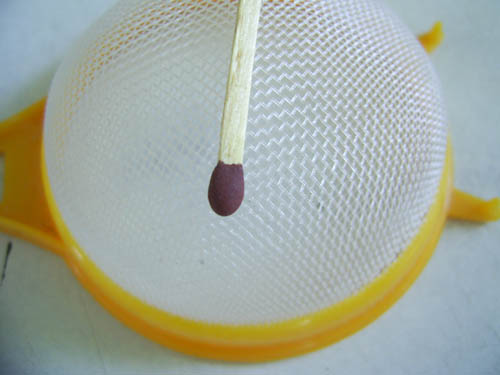
Small plastc strainer (with square mesh not diamond shaped)
Masking tape
and a toothpick (optional)
Black paint (gloss or flat)
Gunmetal paint
First you start with a normal strainer (shown below), then you cut the mesh out using an X-acto knife.
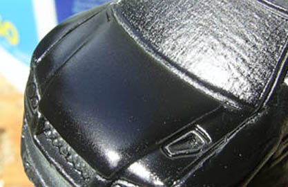
With your bonnet painted black, just a light coat, nothing major...
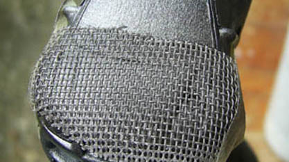
"Mask" the bonnet with a small piece of the mesh. Try to get the mesh as tight as possible to the bonnet else you will lose the effect that the mesh is supposed to cause. Please be sure that yo arrange the lines in the mesh horizontally across the bonnet (mine is a little croked).

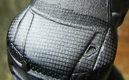
Then you take your can of Gunmetal Grey (here I used Dark metalic bronze) and pass two VERY light coats over the mesh. Too heavy and the lines may be too pronounced and you'll end up with a checker board.
And you end up with this once it's dry
It looks rather crude now, but once you mask the bonnet and continue the paintjob as normal.
Personally I prefer to do this before the paintjob as it is less hassle. All you have to do is mask it when you're finished and continue painting as normal. Once it's done you'll love the results.
Don't throw the mesh away cuz you can use it over and over, as long as you didn't gum it up by applying too much paint.
There you have it...CF bonnets for all your custom bits.
Maxx
You'll need:
X-acto knife
Small plastc strainer (with square mesh not diamond shaped)
Masking tape
and a toothpick (optional)
Black paint (gloss or flat)
Gunmetal paint
First you start with a normal strainer (shown below), then you cut the mesh out using an X-acto knife.
With your bonnet painted black, just a light coat, nothing major...
"Mask" the bonnet with a small piece of the mesh. Try to get the mesh as tight as possible to the bonnet else you will lose the effect that the mesh is supposed to cause. Please be sure that yo arrange the lines in the mesh horizontally across the bonnet (mine is a little croked).
Then you take your can of Gunmetal Grey (here I used Dark metalic bronze) and pass two VERY light coats over the mesh. Too heavy and the lines may be too pronounced and you'll end up with a checker board.
And you end up with this once it's dry
It looks rather crude now, but once you mask the bonnet and continue the paintjob as normal.
Personally I prefer to do this before the paintjob as it is less hassle. All you have to do is mask it when you're finished and continue painting as normal. Once it's done you'll love the results.
Don't throw the mesh away cuz you can use it over and over, as long as you didn't gum it up by applying too much paint.
There you have it...CF bonnets for all your custom bits.
Maxx