Page 4 of 5
Posted: Thu Dec 15, 2005 12:02 pm
by steelwoolghandi
Man that is just unbelievable work dude! Truly you are an artist you have outdid yourself in the chassis work man! Thanks for sharing that and well we must have more pictures! lots and lots more....
Posted: Thu Dec 15, 2005 6:28 pm
by Nasphere
Sporttracguy wrote:Here is a close up of one of the U joints, Sorry about the shadows, its sort of tiny to get a decent picture of
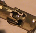
STG
How? What? I don't get it... Do you have a sketch? From what I'm looking at, it just doesn't make sense... It looks good. It looks really good, but dang! lol I just don't get it...
EDIT: Is that left half a sleve too? I think I see another shaft inside that section, it would make sense then... Huh.. Wow..
Posted: Thu Dec 15, 2005 6:50 pm
by Sporttracguy
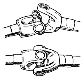
Yeah, ill try and draw up a little diagram,,, on a side not, check out this "U" Joint! I bet it rides smooth,, just wish i knew how to make these on a micro level
 http://www.heli-cal.com/Html/FlxFacts/FFacts73.htm

STG
Posted: Thu Dec 15, 2005 7:25 pm
by Sporttracguy
Ok, lets see if i can explain this without making it way more complicated than it is.
First off, for those that are still confused you need to understand how a U joint works.
This is pretty much what i have constructed in the center portion of that shaft.
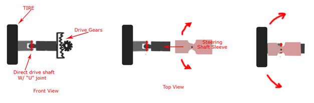
Its crude but it should paint a clearer picture of what is in that tiny brass piece.
Starting off at the far left pictre you see the U joint in the center of the drive shaft. This shaft is mounted directly to the rim and on the other side it is mounted directly to the gears.
In the middle picture you see the outer casing, this hollow tube has a pivot in it to allow for steering and slides over the outside of the center drive shaft. The drive shaft spins freely inside of this tube. The outer tube does not spin, it is connected to the chassis and the steering connectors. The steering connectors pivot the out side tube causing the inner drive shaft to pivot at the U joint.
The far right picture shows the tube in place.
SO what you are seeing in that small brass picture is part of the center drive shaft inside of the outter tube...its just too much brass and not enough context to be clear.
Im not sure if that makes sense or now, let me know if you need me to try and clear things up further
and ill get those other pics up soon
STG
Posted: Thu Dec 15, 2005 9:19 pm
by evoraptor
Nasphere wrote:Sporttracguy wrote:Here is a close up of one of the U joints, Sorry about the shadows, its sort of tiny to get a decent picture of
STG
How? What? I don't get it... Do you have a sketch? From what I'm looking at, it just doesn't make sense... It looks good. It looks really good, but dang! lol I just don't get it...
EDIT: Is that left half a sleve too? I think I see another shaft inside that section, it would make sense then... Huh.. Wow..
What he's saying is that the sleeve on the outside of the U-joint is the steering joint, or the part that swivels in order fo the front wheels to turn. The smaller piece is the U-joint itself.
Posted: Thu Dec 15, 2005 10:27 pm
by Nasphere
Ok, sounds good, I couldn't make the distinction between the "shaft" and "sleeve"... It looks clear now. Thanks folks

That flex joint is a GREAT idea!!!
Posted: Fri Dec 16, 2005 2:24 am
by Sporttracguy
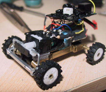
ok, not the best pics but they should work. I still need to get the shocks in there so for now you will see that the chassis may be sitting off center. This is because there are two pivot points making 3 sections. The body is secured to the center section and the front and rear pivot.
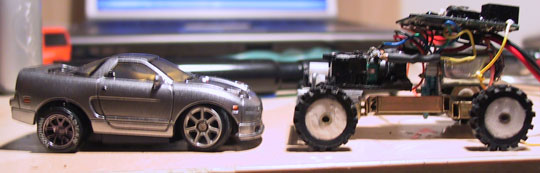
Ok, this pic shows the size difference between a zipzap and my table top truck, they are very close and i would say pretty close to actual scale. Man, i should have finished putting that front wheel on the nsx before i took the picture lol,, all well
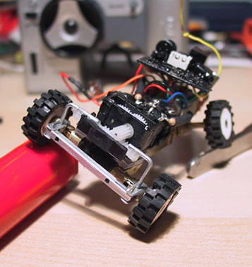
Here you can see the rear axle. The zzse cell is secured to the motor and the motor is secured to an aluminum bracket that i made, it is secured to the center section so it doesnt pivot, the rear axle just pivots below the cell and the motor (lots of room for articulation)

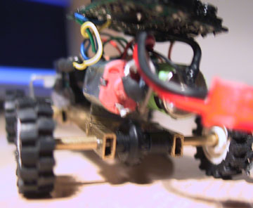
Here is a shot of what it looks like right after the body is removed. You can see the resistors i installed on the steering POT. You can see why the jeep liberty is the perfect shape, the pcb, motor, battery... all fit nicely in the cab of the jeep.
Sorry this pic is so fuzzy,i just wanted to show how the steering looks when it is turned.
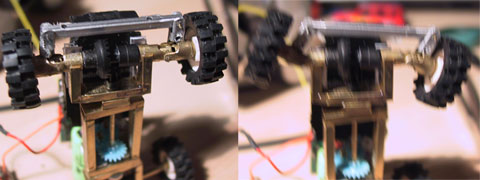
And an articulation shot, the travel is slightly limited by the wheel wells on the body but its still pretty darn close to what you are seeing.
If you guys have more questions please feel free to ask,, there are a few more pictures in my gallery, i didnt feel like posting them all. Next ill have to get the shocks in, paint the wheels and tear it up.
STG
Posted: Fri Dec 16, 2005 2:41 am
by Nasphere
Holy sheemole'!!! That thing's a wicked beauty!!!
<-- (if i had three thumbs)
Posted: Fri Dec 16, 2005 6:27 am
by Xcore
That is AMAZING!

What did you make the chassis out of? Brass?
Posted: Fri Dec 16, 2005 11:58 am
by Sporttracguy
Xcore wrote:That is AMAZING!
What did you make the chassis out of? Brass?
Yep, most of the chassis is brass,, there are a few little aluminum parts but the aluminum is too soft for most of the project. That and the extra weight of the brass isnt a bad thing for the chassis, helps the crawling alot.
Glad you like it guys
STG
Posted: Fri Dec 16, 2005 12:43 pm
by Zenith

I'm still pretty speechles about this thing. This is better than some of those german ones IMHO.
Posted: Fri Dec 16, 2005 1:55 pm
by Tuner1989
Fucking amazing job STG
That is a great display of creativity and hard work i love it!
Posted: Sun Dec 18, 2005 6:29 pm
by Finks
Wow, just wow. Dude, that's a total work of art.
Posted: Sun Dec 18, 2005 8:28 pm
by Clint
The "joint within a joint" axle setup you have designed is brilliant.
We definitly need to see some video of this bad boy in action.
Posted: Sun Dec 18, 2005 11:00 pm
by betty.k
at this scale you could totally get away with springs
even rubber tubing glued in place or heat shrink.
when i wuz a pup i made a balsa boat that was powered by a 130 motor.
the motor and prop shaft were joined with rubber tubing, it never slipped or came apart