Page 1 of 1
Replace watch batteries with AAA? (now with pictures!)
Posted: Mon Jun 16, 2008 3:44 am
by Smoke&Mirrors
So for whatever (secret) reason I'm thinking of replacing some watch batteries in a micro with AAA. My question for all of you who can answer it is, if the batteries (LR44, x2) are 1.5 volts each and there are two of them for a total of a 3 volts, can I just use two AAA's wired in parallel (right next to each other or can I use the two AAA wired in series (end to end)? Also, does the mah matter, the batteries I would use would be 800 mah. Sorry if my description is a little lacking. Let me know if I need to clarify anything.
Posted: Mon Jun 16, 2008 5:35 am
by betty.k
it depends if the watch batteries are wired in series giving you 3v.
if so then yes, wire the aaa's in series and you should be fine.
if you wire the aaa's in paralel then you wind up with a 1.5v 1600mah pack.
wiring in series increases the voltage while leaving the mah rating intact, paralel will increase the mah rating and leave the voltage the same.
Posted: Mon Jun 16, 2008 5:40 am
by Smoke&Mirrors
Ok, makes sense. The watch batteries are wired in series so I'll maintain that with the AAA's. Thanks betty.k. Also, I don't know how much help you can offer, but I'm trying to replace the steering coils with just a single motor, but when I wire the motor to the same areas on the PCB as the coils, the motor only works one way (right on the TX). Do think that's my doing or the way the coils were set up. I can provide pictures if/when necessary.
Posted: Mon Jun 16, 2008 9:08 am
by betty.k
unfortunately you can't replace steering coils with a motor that goes forward and backwards, the curcuits required to drive each are different.
a steering coil is simply an electro magnet, you either turn it on or off.
a motor that can spin both ways requires a curcuit known as an "h-bridge" which is 4 transistors wired up a certain way.
Posted: Mon Jun 16, 2008 3:01 pm
by Smoke&Mirrors
Well isn't that a pisser, especially since I already ripped out the coils and wired in the motor. Well at least now I know, as always, thank you betty.k for your expertise.
Posted: Mon Jun 16, 2008 6:28 pm
by Smoke&Mirrors
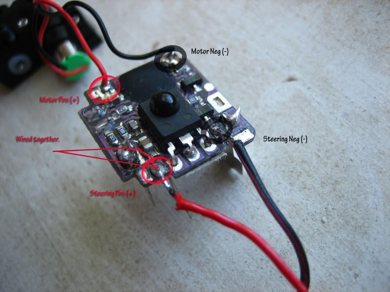
Now I'm having a little issue with the coils. I've tried to re-wire them as I remembered they were. There were four wires coming from the coils, the black enamel coated wire went to the negative terminal and then the the red enamel coated wire went to the positive terminal. The other two wires, which were bare, were glued (I think) to the positive terminal and wired to the area labeled on the picture next to the positive wire. My problem is that while my multimeter shows a current running from terminal to terminal, I still am getting no electromagnetism from the coils. Any ideas?
Posted: Tue Jun 17, 2008 3:52 am
by betty.k
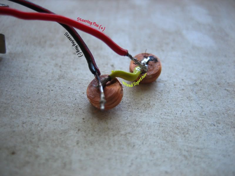
i think you have it wired slightly wrong. here's how it should look:
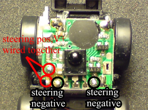
one positive wire from each coil should be soldered to the V+/steering+ pad.
then the 2 negative wires go to the 2 separate steering- pads.
Posted: Tue Jun 17, 2008 2:31 pm
by Smoke&Mirrors
Thanks betty.k, that helps a lot, I'll try that up and report back.