Page 2 of 2
Posted: Wed Oct 15, 2008 6:42 pm
by ibjamn
Looking good

I like the faded look of the old paint. And the model body paint matches it nicely


Posted: Mon Nov 03, 2008 12:37 am
by 45tr0
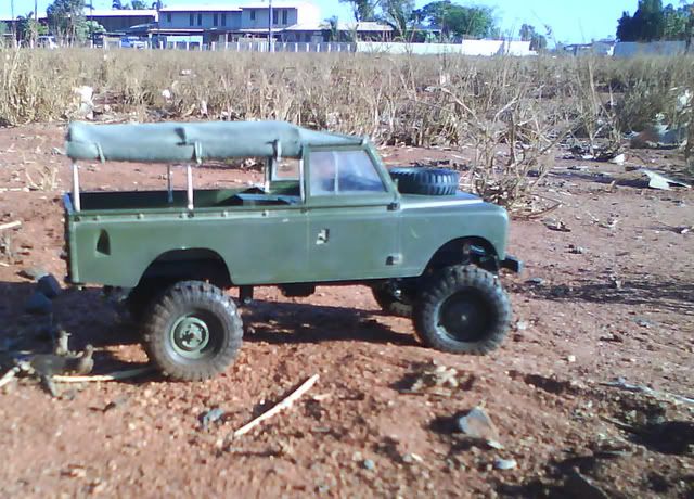
Here's the latest update, sorry about the crappy cellphone pics, my girl's gone away on holiday and taken our digicam with her.
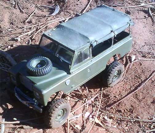
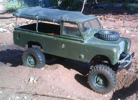
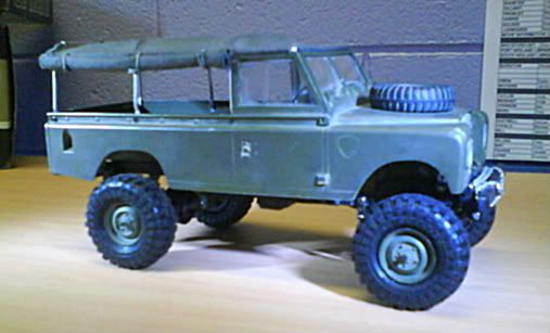
I got the softtop finished - it's 1/16" alloy tubing,, pressed, drilled and screwed together with micro-t screws. I tried same diameter in brass rod, but prefer the alloy tubing as that's what is authentic on my 1:1. (not much roll-over protection, i know!)
The "canvas" is an old fishing shirt I had that just happened to be the right colour.
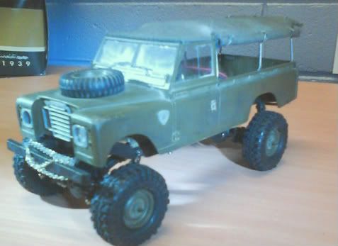
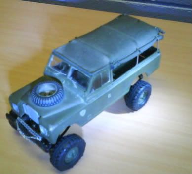
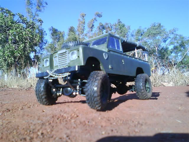
Aoshima swampers came in and fitted with LR kit rims - ride height is still the same, but they fill the guards a lot better now.
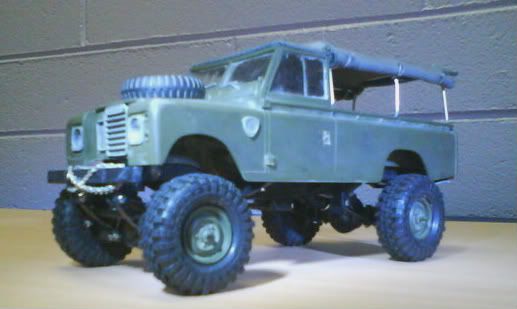
Still to come are electrics - chasing the right size RX & TX - if i can get just the right size, i'll sling them underneath the seats and disguise them as under-seat fuel tanks, ala the 1:1
Posted: Mon Nov 03, 2008 7:44 am
by ibjamn
Wow, the tires are just right for it. Looks great.
I still think that Micro-T electrics would do fine in there, and the all in one designed ESC and RX would be easy to hide.
Now all you need is some minor detailing accessories to complete it.
Posted: Mon Nov 03, 2008 5:59 pm
by crazydave
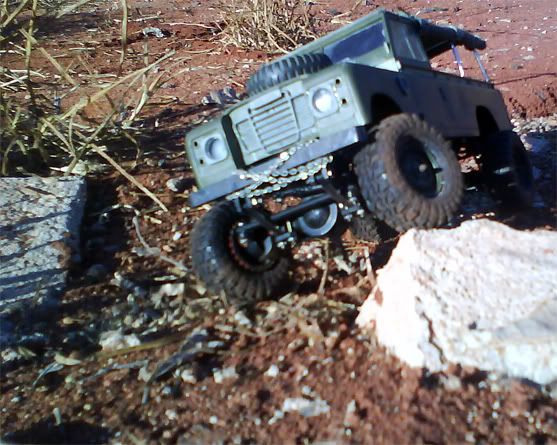
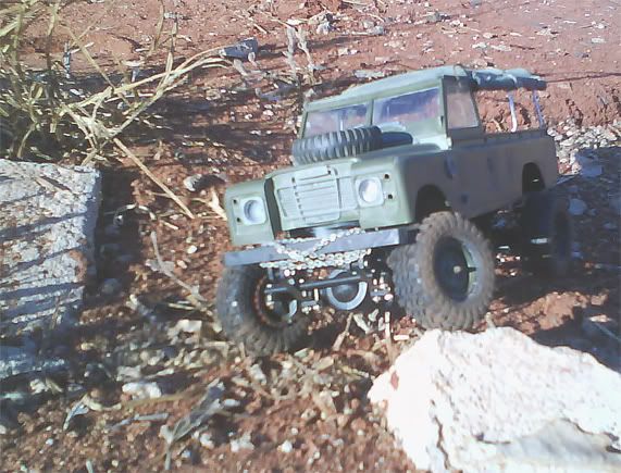
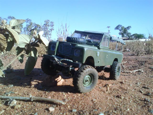
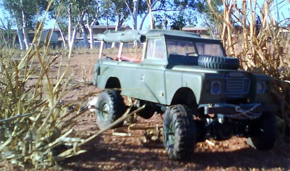
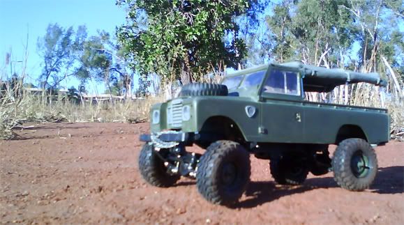
I can't believe how realistic that came out. Some shots of it in its enviroment would be awesome.
Posted: Mon Nov 03, 2008 7:03 pm
by 45tr0
i'm really happy that the tyres were the same ID as the LR kit rims - I cut the rims down to a fascia and i'm really happy to keep the same "military" rim look as my 1:1.
My concern with the micro-T electrics was the servo - i haven't got my head around converting a 3 wire servo to work with the 5 wire board... although to be able to use the light kit available for the Micro-t would be pretty sweet....
Does anyone know the deal with the wiring?
I am still considering the micro T 3-wire RX and a small ESC to go with it... RX and battery under a false floor, small speedy tucked under the driver's seat as a fuel tank.
Thanks Dave - i'm on it for some outdoor shots this afternoon
Posted: Wed Nov 05, 2008 5:49 pm
by 45tr0
Posted: Wed Nov 05, 2008 10:17 pm
by redrustbucket
That's dope. The landscape around you is really cool as well. Always wanted to check out Australia esp. since it's loaded with cruisers!
Re: WIP - my SSMT build
Posted: Thu Jan 29, 2009 7:50 am
by 45tr0
okay guys - i give up and need help!
I've been trying to convert a regular micro servo to work on the 5 wire micro T PCB, and can't get the fuckin thing right. I've killed three micro servos now and the damned thing is just beyond me - call me retarded, but I just cant get it right.
Any of you pimps reckon you could work your magic? I'll gladly pay for the servo, etc, but I've reached the point of frustration that I'm about ready to abandon this whole fucking project - over a goddamn servo!
I need the wiring to be about 6 inches long to reach into the bed to hide the board, and had used a strip of computer ribbon-wire to extend the wiring - but i'm just not sure what i'm doing wrong.
Somebody? anybody? PM me please

Re: WIP - my SSMT build
Posted: Fri Jan 30, 2009 8:36 am
by crazydave
Sorry I missed the pics before. Those look awesome.
Hey, have you had a chance to meet up with your Land Rover group? I bet they'll love it.
As for your servo, I've never done it myself, but from what I under stand, you have the positive, ground, and signal from the standard 3-wiresetup, then there's the 2 motor wires.

Re: WIP - my SSMT build
Posted: Fri Jan 30, 2009 12:05 pm
by Sporttracguy
Micro T pcb:
Gray and blue are + and - for the motor in the servo
The other three wires are for the pot. You have to bypass the board in the servo and wire directly to the motor in the servo(gray and blue) and wire directly to the pot in the servo with the other three wires...at work right now, ill find out the order when i get home tonight.
Edit: so I took a look at my setup and it turns out I "unwired" it...anyways, trial and error should work
You said that you fried several servos? What exactly did you kill? If it's the board I have good news, you don't need the board...
You have to bypass the servo board because the micro t board has the servo guts wires into it.
STG
Re: WIP - my SSMT build
Posted: Mon Feb 02, 2009 2:00 am
by 45tr0
STG - Yup, so i had the motor wires in the right place, and the circuit board removed, but the only result i got was either a servo that span uncontrollably and stripped out the gears, or a complete non-response from the board (including throttle) depending what order i connected the other three to the pot. it all worked again when the servo lead was disconnected, so i'm hoping i haven't cooked anything on the main board.
I tried every combination i could think of wiring up to the pot, and got nothin...
Re: WIP - my SSMT build
Posted: Mon Feb 02, 2009 11:53 am
by Sporttracguy
Interesting
Well having the servo spin continuously may be a result of the pot not interacting correctly with the gears. The pot has to be installed correctly so that it will spin with the gear and respond back to the pcb. If i get some time tonight after work ill sit down and wire one up,,,see if i can get better results

STG
Re: WIP - my SSMT build
Posted: Sun Feb 15, 2009 7:29 pm
by ynad
Looks great, very scale like.