W.I.P. my h1 humvee diary
-
honda_s2000
- bitNinja
- Posts: 883
- Joined: Sat Oct 30, 2004 5:42 pm
- Location: New Zealand
-
frizzen
- bitDisciple
- Posts: 1730
- Joined: Wed Aug 03, 2005 7:48 am
- Location: Big Left Turn, Indiana
- Contact:
- betty.k
- bitPimp
- Posts: 4090
- Joined: Fri Dec 26, 2003 4:52 pm
- Location: la la land
- Contact:
hell yeah, 10 seconds on the concrete versus 30 mins with fine sandpaper!no concrete-floor sanding for this one, huh??
i don't quite remember, probably out of some old electronic thingo that i butcher for parts. walkmans are a great source of micro mounting hardwareWhere did those screws come out of?
i forgot to mention what i used for the h plate, it's plastic from a floppy disc.
- ibjamn
- bitDisciple
- Posts: 1057
- Joined: Thu Mar 30, 2006 9:09 pm
- Location: right here, waiting
Yeah. I've been harvesting some stuff out of old broken car audio cd players.betty.k wrote:i don't quite remember, probably out of some old electronic thingo that i butcher for parts. walkmans are a great source of micro mounting hardwareWhere did those screws come out of?
Great for odd-ball gears too.
You have got to see the stuff in a Indash 6-disc changer
- betty.k
- bitPimp
- Posts: 4090
- Joined: Fri Dec 26, 2003 4:52 pm
- Location: la la land
- Contact:
got some bodywork done today.
busted out the floppy disc plastic and made a slope back, i wanna keep the panel lines.
the beauty of doing a rough military style is you can get away with some rough patches
i ground down the hood vent and filled the chassis tab holes too.
masked up the windows and threw down a quick coat of primer.
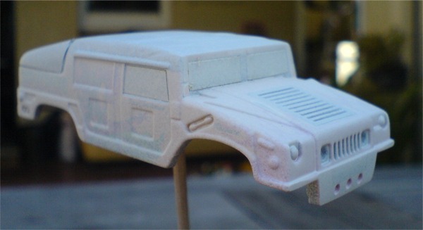
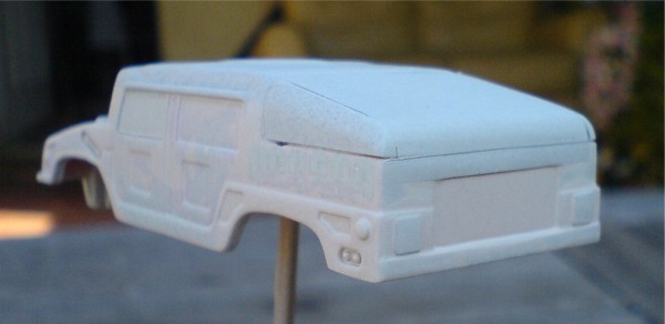
aside from a tiny bit more sanding i'd say it's done. i'll finalise the mounting then finish painting it.
busted out the floppy disc plastic and made a slope back, i wanna keep the panel lines.
the beauty of doing a rough military style is you can get away with some rough patches
i ground down the hood vent and filled the chassis tab holes too.


masked up the windows and threw down a quick coat of primer.


aside from a tiny bit more sanding i'd say it's done. i'll finalise the mounting then finish painting it.
-
honda_s2000
- bitNinja
- Posts: 883
- Joined: Sat Oct 30, 2004 5:42 pm
- Location: New Zealand
-
ph2t
- bitPimp
- Posts: 1979
- Joined: Tue Mar 25, 2003 6:33 am
- Location: taco city
- betty.k
- bitPimp
- Posts: 4090
- Joined: Fri Dec 26, 2003 4:52 pm
- Location: la la land
- Contact:
yeah, olive drab military look. maybe camo if i can be bothered 
so on with the chassis.
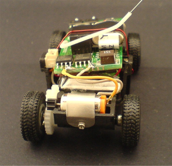
i used some thin metal (floppy disc again) to make a motor cover which hooks over the idler gear axle and is held in place with a screw.
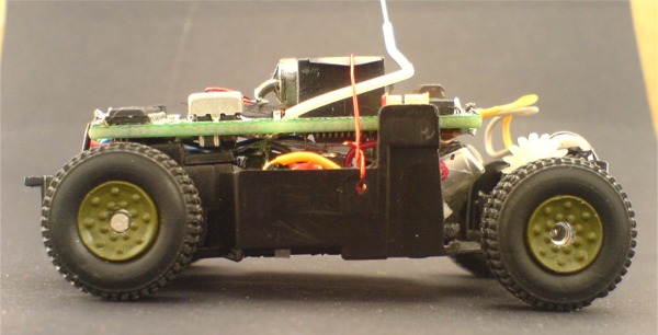
i also ground down the chassis where the knuckles go to gain more suspension travel up front. i trimmed some off the tie rod also and i got about .75mm more travel out of it.
you don't want to go too far or the knuckles will pop out at the top.
i removed the stock charging plug from my cheapy heli, as you can see it's tiny so it won't take up much space at all.
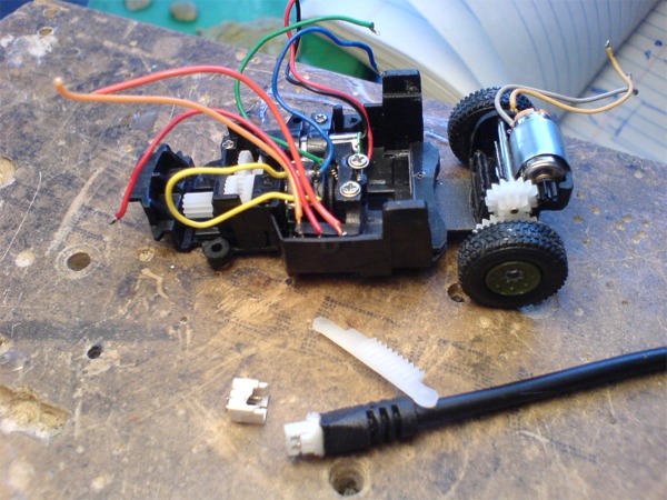
i installed the guts again, glued the charging socket into the chassis and mounted the lipo. there was more room than i originally planned so i was able to lay the lipo back almost flat.
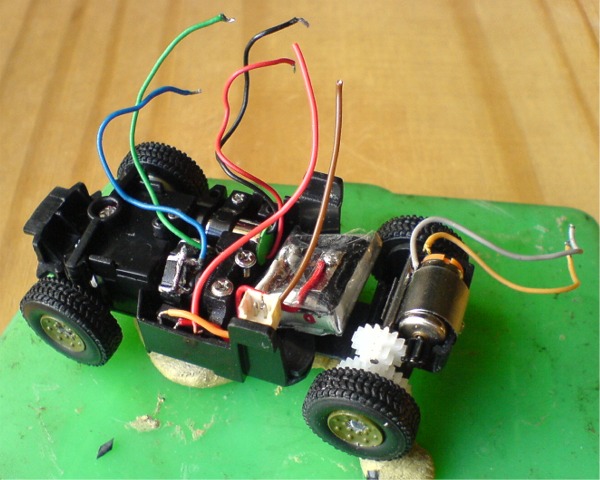
i've wired the switch so the the cell is either connected to the charging socket or the pcb.
to prep the pcb for final installation i bridged the 2 tabs where the switch normally is, already a switch on the main power.
i removed the crystal socket and hardwired a trimmed crystal straight to the pcb.
for the steering (as mentioned in sat4life's mr01/zzse mod) you will need to connect a 10k ohm resistor across the servo pot tabs as the mr02 pcb uses a 5k ohm pot and the zzse pot is 10k ohm.
wiring the 2 resistors in parallel (zzse pot, 10k ohm resistor) halves the resistance and doubles the wattage.
end result is a 5k ohm zzse pot.
there was some servo shaking at first but fiddling with the steering trim on the pcb fixed it.
topped it off with a guitar string aerial.
all it needs now is for me to paint the centers of the wheels, the silver sticks out like dog's balls!
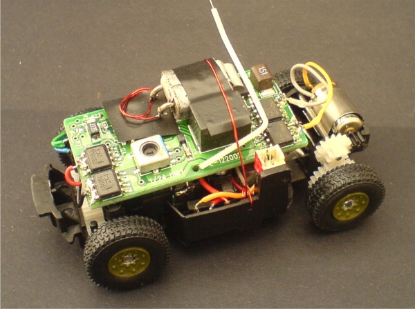
just a little more clearance than stock
so on with the chassis.
i used some thin metal (floppy disc again) to make a motor cover which hooks over the idler gear axle and is held in place with a screw.
i also ground down the chassis where the knuckles go to gain more suspension travel up front. i trimmed some off the tie rod also and i got about .75mm more travel out of it.
you don't want to go too far or the knuckles will pop out at the top.
i removed the stock charging plug from my cheapy heli, as you can see it's tiny so it won't take up much space at all.

i installed the guts again, glued the charging socket into the chassis and mounted the lipo. there was more room than i originally planned so i was able to lay the lipo back almost flat.

i've wired the switch so the the cell is either connected to the charging socket or the pcb.
to prep the pcb for final installation i bridged the 2 tabs where the switch normally is, already a switch on the main power.
i removed the crystal socket and hardwired a trimmed crystal straight to the pcb.
for the steering (as mentioned in sat4life's mr01/zzse mod) you will need to connect a 10k ohm resistor across the servo pot tabs as the mr02 pcb uses a 5k ohm pot and the zzse pot is 10k ohm.
wiring the 2 resistors in parallel (zzse pot, 10k ohm resistor) halves the resistance and doubles the wattage.
end result is a 5k ohm zzse pot.
there was some servo shaking at first but fiddling with the steering trim on the pcb fixed it.
topped it off with a guitar string aerial.
all it needs now is for me to paint the centers of the wheels, the silver sticks out like dog's balls!


just a little more clearance than stock

Last edited by betty.k on Wed Oct 04, 2006 8:34 pm, edited 1 time in total.
-
Maxximum Attack
- bitDisciple
- Posts: 1798
- Joined: Thu Jul 31, 2003 7:15 pm
- Location: Barbados
-
honda_s2000
- bitNinja
- Posts: 883
- Joined: Sat Oct 30, 2004 5:42 pm
- Location: New Zealand
- Clint
- bitPimp
- Posts: 519
- Joined: Sun Jul 06, 2003 7:20 am
- Location: Albany, NY
- Contact:


