
The ‘Crip Cap’ (In The Car) Mod
by ph2t
I’ve been doing this method on a few cars now and settled on this being my standard for all my cars when increasing the range. With the method outlined below I can achieve 10 meters (approx 30 feet) indoors.
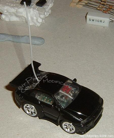
First of all, here’s my stock MS 49Mhz with a Skyline shell and crapola antenna, it will be the guinea pig for today’s little exercise…
Now let’s remove the shell and carefully prize the plastic pcb cover off. For all you Aussie Compact Char-G owners the pcb cover is actually glued so be extra careful. The M?Sizers don’t suffer from this, dunno about Bit Char-G.

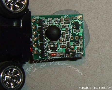
Next, let’s locate the nasty ‘lil bugger, you will see it outlined in red below. NOTE: This is in every car I have seen to date. Unlike the crip cap in the TX which varies at the best of times. Upon closer inspection you will notice that the solder work done on this surface mount capacitor is messy and not as clean a job as the rest of the circuit board. There are theories going around that TOMY added this cap after production due to the range being too good… go figure…

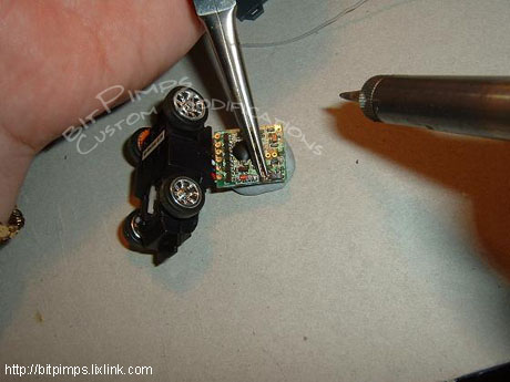
Prize open the pcb from the chassis CAREFULLY, you don’t want to break anything, especially little steering wires… This is done from the side OPPOSITE to all the solder pads that say L R B F V+.

Once you have opened the chassis up sufficiently, flip it over and secure it to your bench top using some plastic putty stuff, I’m using Bluetac in this example. You will need the pcb to be secure to give you the leverage you will need to continue…

Now, here’s the trickiest bit of the whole procedure. Make sure you have the capacitor in the grip of some needle-nose pliers, using a soldering iron heat of the solder pads on each side of the capacitor and slowly work it loose. Be careful to not damage other components close by.
Ahhhh, now isn’t that better? See below. No more @#$%^ cap!
Look how bloody small the thing is, shown here next to a steering knuckle.

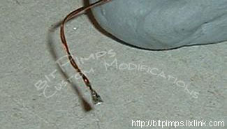
Now that the hard parts done, let’s add a new antenna. For those people paying attention I had removed it earlier. Shown below is some enameled wire (0.25mm dia) I’m using for an antenna, it works well for its purpose…

Remember to always TIN your wire first to allow for an easier solder job when connecting it back onto the pcb. I cannot stress this enough.
And you’re done…

With the cripple capacitor removed and a new antenna added, we’re ready to hit the town.

Not without our crew though!

