
ZipZap SE Duty Cycle Mod
by codesuidae
- Summary
- Difficulty Level
- Parts Required
- Tools Required
- Tools Recommended
- Description of Modifications
- Reference Diagrams
- Procedure
- Preperation
- Testing
- Disassembly
- Identification of Components
- Installation of DC board
- Inspection
- Assembly
- Testing
- Parts Sources
- DCMod Service
- Credits
Summary
The ZipZap SE provides power to the drive motor using Pulse Width Modulation, or PWM. This is a method of controling the power to a device by rapidly switching the power on and off. This rapid switching allows the SE to run its motor at several different speeds. The problem is that at maximum output the SE only turns the motor on for 30% (for first and second generation cars) or 56% (for third generation cars). This means that the SE is much slower than it could be. This mod intercepts the signal that turns the motor on, measures it, and creates a new, longer output signal that allows the motor to run at 100%.
The board reduces the power of the first step, to provide better low-speed control of the car when using very fast motors, and raises the output of the last two steps to 75 and 100% to provide roughly 50% more power to the motor for high speed operation.
The DC mod provides a performance increase of about 30 to 60% without the need for replacing the drive transistors with MOSFETs. However, MOSFETs still can provide a performance increase. The DC mod works with or without MOSFETs.
Difficulty Level
5 out of 10. Installation of the mod is fairly easy, requiring the removal of one surface mount resistor.
Parts Required
For each motor control circuit (h-bridge) to be upgraded, you will require:
- 1 DC mod board
- 1 150 ohm resistor (if installing on a car that is not FET modded)
Tools Required
The following tools are required to perform this mod.
- Soldering iron, 15-35Watts, cone tip
- Solder
- Hobby knife or small jewlers screwdriver
Tools Recommended
The following tools, while not absolutely necessary, are recommended to make the mod easier.
- Magnifying lens, hobby clamps or putty
- Small container for parts
- Soldering flux
- Desoldering braid
- Multimeter (Volt-Ohm meter)
- RPM meter
Description of Modifications
Reference Diagrams
You may refer to the following diagrams for component naming and locations on the PCB.
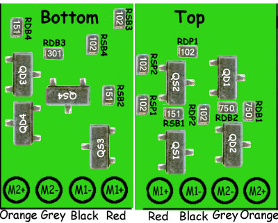
The components are not labeled on the board, refer to this diagram for placment. There may be slight variations from board to board, so you may want to verify connections to other components if your board varies from what you see here.
This is an illistration of the top and bottom of the ZipZap SE PCB. The components are designated using the following naming convention:
Description of Modifications
Reference Diagrams
You may refer to the following diagrams for component naming and locations on the PCB.
The components are not labeled on the board, refer to this diagram for placment. There may be slight variations from board to board, so you may want to verify connections to other components if your board varies from what you see here.
This is an illistration of the top and bottom of the ZipZap SE PCB. The components are designated using the following naming convention:
- First letter ‘Q’ indicates a transistor
- Second letter ‘D’ indicates Drive
- Second letter ‘S’ indicates Steering
- First Letter ‘R’ indicates a resistor
- Second letter ‘D’ indicates Drive
- Second letter ‘S’ indicates Steering
- Third letter ‘B’ or ‘P’ indicates a Base or Pullup resistor

H-bridge Schematic 1st Generation. Inputs from the controller chip are at the unconnected ends of RSB3, RSB4, RDB3 and RDB4.
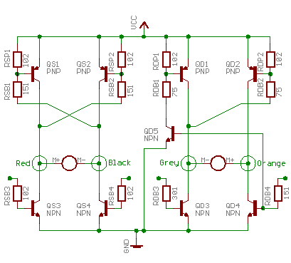
H-bridge Schematic 2nd and 3rd Generation. Same as above, but with the addition of QD5 to control the base of QD1.
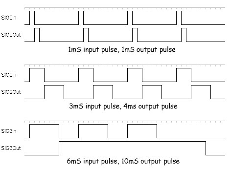
This diagram shows three examples of the input to the DC mod chip next to the output generated for that input. The duration of the input pulse is measured, and as soon as it stops the output pulse begins. The length of the output pulse is determined by a lookup table in the mod chip.
In the third example the top waveform represents the maximum output generated by the third generation of the ZZSE, a 56% duty cycle (a 5.6mS output pulse with a 10mS cycle time). The lower waveform is the 100% duty cycle the DC mod board generates.
Procedure
Preperation
The leads to be soldered are very small, so it is essential to have a properly configured soldering iron. If the tip of the iron is not clean and sharp, use a file on the cold iron to produce a pencil-like point (this will remove the protective coating of the tip, but this is generally not a problem if the iron is kept properly tinned). Heat the iron to operating temperature and clean with a wet rag or sponge, then apply enough solder to produce a uniform coating on the tip and again clean the tip on the rag or sponge. The tip should be left with a very thin coat of solder, but no drips.
Testing
Start by testing the performance of your RC car. If you have an RPM meter measure the unloaded acceleration and top speed of the car. You may also time the car over a fixed distance, or measure the maximum incline the car can climb. Select conditions (track surfaces and distances) that can be replicated for comparison testing. Test with a variety of motors if you like.
Disassembly
First verify that the car is turned off. Remove the battery as a precaution. Shorting leads while power is applied can destroy components and ruin the car.
Using a small jewelers screwdriver remove the two screws holding the PCB. One is located near the front center of the PCB, the other is at the rear, near where the antenna is connected. Remove the small plastic clip held down by the rear screw and place the screws, clip and black plastic retainer from the front of the PCB and place them in a small container (you may also draw a large diagram of the car and place the parts on the diagram to make replacement very easy).
To see the bottom of the PCB, carefully lift the PCB off the chassis and note the positions of the wires. When reassembling the car you will want to replace the wires as you found them for the best fit. Flip the PCB over to expose the components on the bottom the board. Use small clamps or putty to secure the board and chassis to the work surface, but be careful not to place too much tension on the wires. Wires pulled off of the board can usually be fixed, but sometimes it can take some very delicate soldering!
Identification of components
Recognizing Transistors:
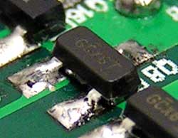
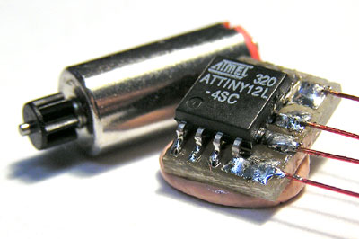
This is a typical surface mount transistor. At the right side of the image two of the three legs can be seen soldered to the PCB. The third leg is in the center of the opposite side of the device.
Recognizing Resistors:
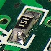
This is a typical surface mount resistor. The value of the resistor is printed on the top. The first two digits are the first to digits in the value, the third digit indicates the number of zeros that come after the first two digits. The value of the resistor at the right is 150 Ohms.
Installation of DC board
Component Removal:
Locate the RDB4 resistor on the bottom of the PCB using the diagrams above as a guide. Apply a small amount of flux to the ends of the resistor and use desoldering braid to remove the solder holding the resistor to the board. The flux will aid in complete removal of the solder. After both ends have been removed, gently push the resistor sideways with the tip of the soldering iron. It should slide off the board with very little pressure.
Connections:
If the DC mod board is to be installed on a car without the MOSFET mod the output to the H-bridge must go through a 150 ohm resistor. This is to limit the current supplied to the base of the transistor. The surface mount resistor RDB4 may be used for this purpose, or a new resistor may be supplied. Any sise resistor will serve, but for space conservation the smallest available should be used.
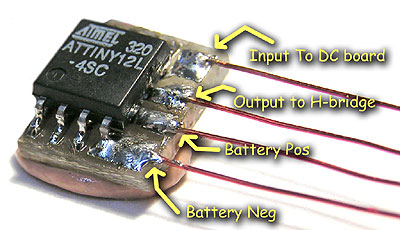
The DC board requires four connections, power, ground, input from the ZipZap CPU and output to the H-bridge.

The input and output connections must go to the bottom of the board, the power supply leads can go to the top or bottom. As show nere the power supply leads have been attached to suitable ground and power connections on the bottom. The board may be powered directly from the battery or from the 3v booster on the SE. Here it is connected directly to the switched battery positive input to the PCB.
Inspection
After all the new components have been installed, use a magnifying lens to carefully inspect all soldering and components. Verify that no solder has formed a ‘bridge’ to adjacent pads, and that all components are properly connected.
Assembly
Reinstall the battery and return the PCB to its original position. Carefully arrange the wires under the board as you observed them when removing the PCB. Reinstall the front and rear PCB clips, and don’t forget to thread the antenna back through the strain-relief in the rear clip. Do not over-tighten the screws, the plastic strips easily and can be difficult to repair.
This is the reassembled car with the mod board installed above the motor clip. This seems to be a good location for most body tops, but the board can be installed anywhere it fits. If the motor is to be changed frequently a different location might be prefered.
Testing
Refer to the notes taken during inital testing and retest the vehicles performance under the same conditions. By compairing results you will get a quantitive assessment of the performance improvement, rather than error-prone and subjective qualitive assessments (i.e. ‘it feels twice as fast!’ ).

Parts Sources
The DC mod board can be purchased for $10. If you are installing the mod on an SE that has not been FET modded you will need to supply a base resistor, as detailed in the installation section above.
DCMod Service
If you do not want to, or do not feel you can safely install the DC mod, I can do it for you. I offer DC mod service for $17 per car. I can also do a FET mod at the same time for a total of $30 (save $7 over the individual prices). You pay shipping to me, I’ll pay shipping back to you. It usually takes about 7 to 10 days for the car to make it through the US mail service in the contigious states. I accept PayPal, money orders and cash. If you would like to take advantage of this service, please contact me via AOL or Yahoo IM or email.
