CaboWabo’s Dual Cell Mod
by CaboWabo
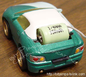
 There are two approaches to this mod, one being to mount the battery on top of the heat sink, the other being to flip the PCB and hide the battery inside the chassis. For this article we’ll be discussing the battery on top of the heat sink approach – this will help us with wheelies!
What you need:
- 2 batteries of the same capacity
- 2 pieces of thin wire
- a soldering iron with solder (paste optional)
- electricians tape
 First off, you’re going to solder a piece of wire from the positive (+) side of 1 battery to the negative (-) side of the other battery. In this image, the positive (+) side of a battery is shown on the left and the negative (-) side on the right. For reference, we’ll call the battery on the left side “battery 1” and the battery on the right side “battery 2”. You may have to use soldering paste or scratch the surface of the battery to get the solder to hold. Don’t let the solder sit too long on the battery or you’ll start to melt the plastic shrink wrap around them.
 Next, you’re going to solder another piece of wire on to the positive (+) side of battery 2. You should make this wire just a little longer than the wire connecting the two batteries. Now you’re going to take the electrician’s tape and wrap up the negative (-) end of battery 1. Once you have that completed, you can put battery 1 into the chassis – with the taped end being on the driver’s side.
There are several little spaces cut out of the chassis that lead up to the heat sink, they’re the perfect size to fit your wires into which will allow for a better fitting PCB cover. Let battery 2 rest on top of the heat sink and guide the connecting wire in to the groove in the chassis. On the opposite side of battery 2, run the wire down to the chassis, and over the battery towards the taped end of battery 1. Slip the wire coming from battery 2, between the prong and the taped end of battery 1. Slide on the PCB cover and you’re done with that part.
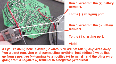
 Now for the controller, we need to modify this to charge our new dual celled car. This the easy part, take off the top of the controller and expose the circuit board as well as the charging station. Solder a wire from the positive (+) point on the circuit board, to the positive (+) point on the charging station. Now solder a wire from the negative (-) point on the circuit board, to the negative (-) point on the charging station. Put together your controller and you’re done!
It should be noted that after modifying your controller, the “on/off” switch is useless. Your controller will always be on, which is fine as long as you don’t have your car docked on the charging station.  The light on the controller will not come on anymore either, which is fine. Just plan on charging for around 1 minute 30 seconds to 2 minutes for a full charge.
The diagram to the right shows how 2 batteries inside the car would be wired in a series.


